2018-03-07 Remote controlled tank, part 2: The boards, or A Crash Course in Debugging Hardware.
They're all here!

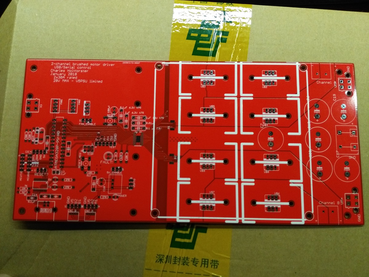
Monday morning, A large package arrived in the mail, containing a solder stencil and ten shiny red PCBs.
They were ordered from JLC PCB in 2 ounce copper. And they are beautiful. They were ordered while China (Yes, the whole country) was closed on holidays, so I had plenty of time to spot my errors, as noted in the last post, and bemoan my bad PCB design. Live and learn.
The next day, the components arrived from DigiKey. I immediately went and tried to solder on the high-power side and the test lines (TEST headers, six pin header), as well as the fault LEDs.
Soldering HTSSOP38 is a bit difficult by hand. Next time, a reflow oven will be used. The gate resistors, which I'm uncertain about needing even in the full build, were jumpered with lead offcuts from the MOSFETs. The current sense resistors and fault LED components were attached. Some wires were soldered to the power connection pads and the motor terminals for testing. Also, the holes for the motor terminals are too small for the terminal blocks I purchased, so I will have to resize those holes. Luckily, both of their pads are on the top side of the board.
Also, I forgot to bring the bulk capacitors with me to the WARG lab where I was assembling the boards, so that briefly remained detached.
Practically drooling in anticipation, I hooked up a computer power supply to the input, a drill motor to the A-channel output, and an Arduino to the test input lines. After throwing on a pair of safety glasses, I punched in a motor speed through the serial connection and waited.
Nothing happened, of course, because I found another board error: The SLEEPn line was not broken out to the test headers, or even pulled high. I shoved in a test lead to connect it to the 5V rail, and tried again.
Success!
It spun up with the typical 490Hz whine of the Arduino's PWM channel. It stopped when zero was sent. It was wonderful.
But, this is a bidirectional driver. So, I tried speed -100. And it worked for about a second, before being replaced with a faint 490Hz hum.
Success...?
And so began the grand debugging adventure.
With the control lines connected in one direction, it worked perfectly forward, but intermittently in reverse. With the control wires swapped to reverse the direction shown to the motor driver, it worked with positive speeds, but the motor would not turn "backwards". This eliminated a software error on the Arduino, or a failed connection to the board from the headers.
My next step was to turn the motor around and return the forward control lines to the forward speed. It worked in forward, it stopped, but it only gave the same faint hum in reverse (negative speed).
With that having narrowed down the search, I turned to wiggling the board wildly with the speed set to -30.
It would occasionally work. And then stop. Then work. There was no rhyme or reason. Touching it in one spot would, for a ten second span, reliably activate the motor. Then that would stop working. This continued for several minutes, before I concluded that that the problem was probably not a cold solder joint.
The bigish guns
Recently, I bought a knockoff DSO138 oscilloscope from eBay. It's pretty great. For the price, I would absolutely recommend it.
This seemed like the perfect use for such a tool, so I broke out the scope and the Canadian Tire analog multimeter.
According to the scope, the signals leaving the Arduino and arriving at the headers were correct. Clean, well-behaved square waves with a duty cycle between 100% and 0% depending on what I sent.
My next thought was to connect it across the motor and see what happens. In forward, the motor behaved well, giving off textbook flyback diode curves.
In reverse, things were a little less pretty.
The voltage across the motor was zero 99% of the time, taking microsecond-long jumps up to 12V roughly every 2 milliseconds. And then someone down the hall would sneeze - or something - and the motor would start working, the waveform would behave correctly for a tenth of a second, looking exactly like the forward waveform but upside-down, until the problem reared its ugly head again.
PWM, WTF?
So, I aimed at the next components in the stack, the MOSFETs.
With the scope in DC-coupling mode, I probed between gate and source for each MOSFET while running forward (Square waves on the one, constant 12V on it's opposite, and zero on all others), and stopped (0v on all). Then I checked what happened in reverse.
The gate signal to the low-side positive MOSFET was a mess. It was a 490Hz pulse, about a microsecond across. Which looked strangely familiar.
At this point, it was 11:45, and I opted to sleep on it.
The next day
At breakfast, I remembered reading an article that discussed communication link failures and the unpredictable output from them. One of the weirder ones I remember is that a micro-fractured wire, or PCB trace, can behave like a capacitor, and turn square waves into one-shots up and down on falling and rising edges.
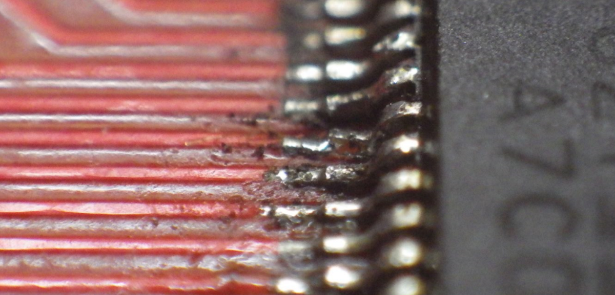
I broke out my camera, a Ricoh WG3, and used its astonishingly powerful macro feature to take a close up look at the traces.
Craaaaaaaaaaaaaaaaaap.
Oh.
In the fifth trace from the top of the image, there's a clear yellow line running bottom left to top right across the trace. That could be the magical broken trace! There's also another line across the trace immediately before the pad. And the pad is crooked.
And on that same line, the pin on the DRV8704 is a touch dog-legged. But it gets better. By which I mean, of course, worse.
The pad is sideways. And not adequately soldered. And covered in excess flux. And, generally, in pretty terrible condition.
And this pin, 11th from the top of the chip, is, (Drum roll please!)

Nailed it!
The A- pin, which needs to be PWMed to get reverse control.
So, one of those issues is causing the problem. Or maybe not, but I cannot find anything else.
Fixin' the damn thing
I brought it back to the workshop and had the friend of mine who had soldered it in the first place take another crack at it.
It did not work. In fact, it got worse - now, neither forward nor backwards on channel A was working. So I brought it back to the Waterloo 3D-print centre, removed the electrolytic capacitors, and threw it in the reflow oven.
This melted the header test strips into a blob and destroyed the driver reset switch, rendering the unit unusable. I could no longer test that board without replacing several components, and the pad for the chip was probably already broken. That was the turning point in the evening.
In the words of Tom Cochrane,
The secret is to know when to stop
I set aside the ruined part, brought out the second of ten PCBs, and reached for the DigiKey box.
In terms of components, I opted to go for broke, deciding that, if I made any mistakes, I would need to place another DigiKey order anyways. If any number of failures is equally disruptive, why not risk them all? So the FT232RL, DRV8704, and two current sense resistors were fluxed, pasted, and daintily placed onto their pads, before being carefully placed into the reflow oven at 250°C for two minutes.
They emerged perfect from far, but far from perfect. Five adjacent pairs of pins on the DRV8704 were bridged, as were two on the FT232, but after a quick treatment with some solder wick and a 700-degree iron, these problems were no more.
(Side note: The bridged pins on the 232RL were not noticed until the Arduino used for testing refused to boot when the 5V line was connected. Whoops.)
With the 8704 installed along with all the test pins, testing began. Without MOSFETs installed, the chip would immediately throw a fault. But what fault?
It took around a half hour plus a break for dinner to get the SPI connection working to read the fault register. The documentation for the SPI bus is unclear at best, and misleading at worst, but we managed to get through it. We encountered a magical bug, whereby MISO was staying high no matter what we tried. However, when we came back from dinner, it worked perfectly, and was given no further consideration. It is expected that this bug was due to poor hookups.
After soldering every other component on, everything except reverse on the A-channel worked - it immediately threw a fault when engaged. Since we now had the error register at hand, we could find that it was an overcurrent protection fault, which is triggered by a voltage drop across a MOSFET being too high. Which sounds suspiciously similar to the source not being soldered correctly on a MOSFET. Some more soldering had the board firing on all channels, at top speed.
Victory at last.
What I learned
- Having testable subcomponents is tremendously useful.
- The minimum order quantity on PCBs is, really, a good thing.
- Starting from scratch can save time.
- Never reflow a board with plastic-spaced header pins in it.
- As an addendum to that, never reflow a board with a tactile switch in it.
- There is no such thing as having too many test points.
- Using a reflow oven beats hand soldering SMD every time.
The next steps
The last step to get the device working fully independently is to insert and flash the ATMega328p.
With the motor control circuitry being entirely ready to rock (Except perhaps doubled MOSFETs and gate resistors, but time will tell), mechanical design is the next step. Updates to follow.